The atmospheric counterflow burner setup is used to determine laminar flame speed, extinction stretch rate of premixed fuel oxidizer mixtures. It is also used for soot studies in non-premixed flame.
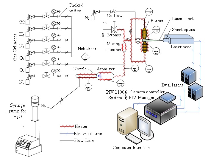
Figure 1. Schematic of the counterflow setup (not to scale)
The experimental setup consists of flow control and mixing system, counterflow burner apparatus, and a DPIV system. The counterflow setup is schematically represented above in Figure 1. Two high contraction ratio contoured burners are arranged vertically, opposing each other. The thoroughly mixed fuel/oxidizer mixture is fed to the burners to form a stagnation flow. A twin-flame is established when the fuel/oxidizer mixture is ignited. Figure 2 below shows the arrangement of the two burner nozzles without and with the flames established. The light scattering seeding particles enables to visualize the flow through the burner nozzles.
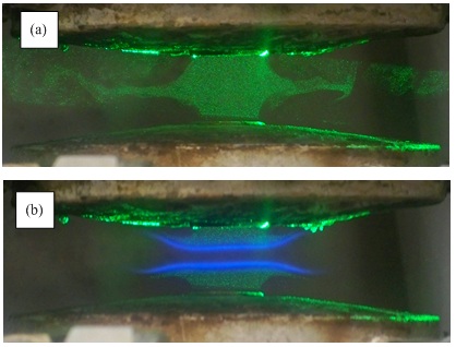
Figure 2. Opposed flow burners shown (a) without and (b) with the twin flames; the light scattering seeding particles visualizes the flow.